¶ TCC Zener board installation
The TCC Zener board is an addon for the 1.3 boards that vastly improves the lockup smoothness of the TCC (Torque converter clutch).
This is only for the old 1.3 Board (Dated 2022), for the new 1.3 Rev B boards, the instructions are printed on the rear
of the PCB
This is not compatible if you use GPIO Pin 23 of the TCU for an input or output speed sensor
This tutorial covers how to install it.
¶ Items required
- Soldering Iron and solder
- Heat gun (For desoldering) - You might be able to desolder the parts instead
- Wire 27AWG or thicker
- Double sided tape
¶ Steps
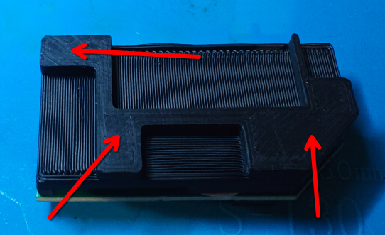
¶ 1. Double sided tape installation
Place double sided tape on the rear of the Zener board mount as shown:
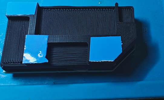
The board should now look like this
¶ 2. Desoldering
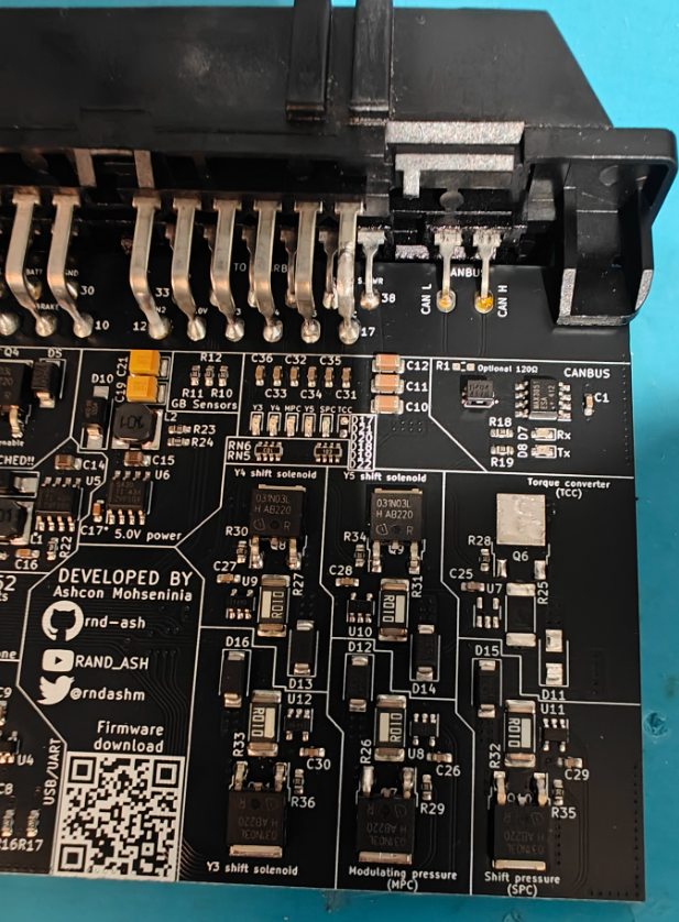
On the PCB, desolder the following components (Highlighted). You can use a heat gun, or a soldering Iron to do so.
- D22 (LED)
- R25 (Resistor)
- U7 (INA180)
- D11 (Diode)
- Q6 (MOSFET)
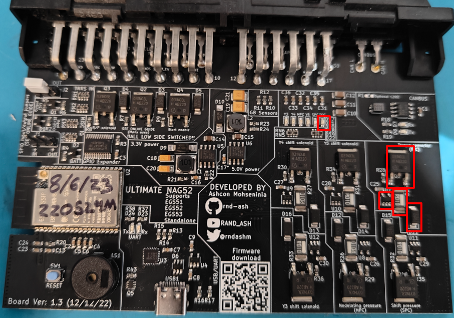
This section of the board should look like so after desoldering:
¶ 3. Placing and wiring
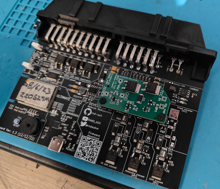
Place the TCC Zener board on the PCB like so:
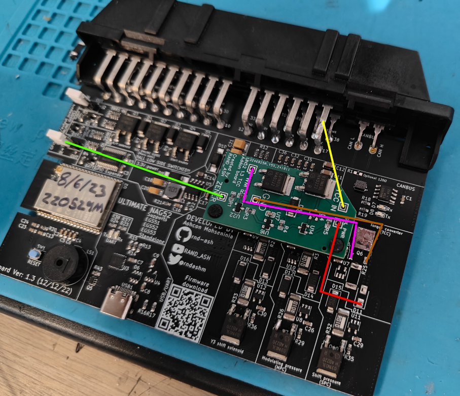
The zener board should now be wired up like so:
| Zener board | Pad (TCU) |
|---|---|
| GND | Right pad of Q6 |
| SOL PWR | Lower pad of D11 |
| TCC IN | EGS connector pin 17 (TCC) |
| PWM | Left pad of Q6 |
| Zener | Middle pin of J1 (Lower jumper) |
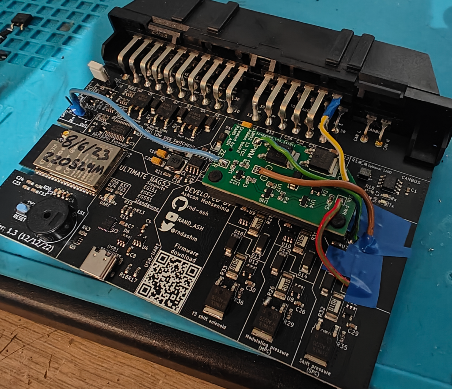
Lastly, protect everything with electrical tape to prevent any potential shorts:
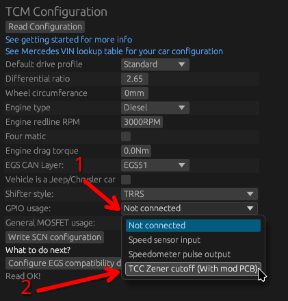
¶ 3. Configuration
In the configuration app, under TCU Configuration, simply select the use of the GPIO pin usage to TCC Zener cutoff