¶ PCB Revisions and schematics
¶ Summary of board generations
- 1.x - Hand assemblable, ESP32 processor based, easy to use for beginners
- 2.x - Under development - Only available via purchase, AEC-Q100 (Automotive grade) components (Firmware is still open source, and schematics will be provided)
¶ V2.0 (Under development)
A complete re-design from the ground up, based on a whole new architecture, which is designed to bring the project in-line with the Siemens EGS units with safety and monitoring.
This PCB is NOT considered hand-assemblable!
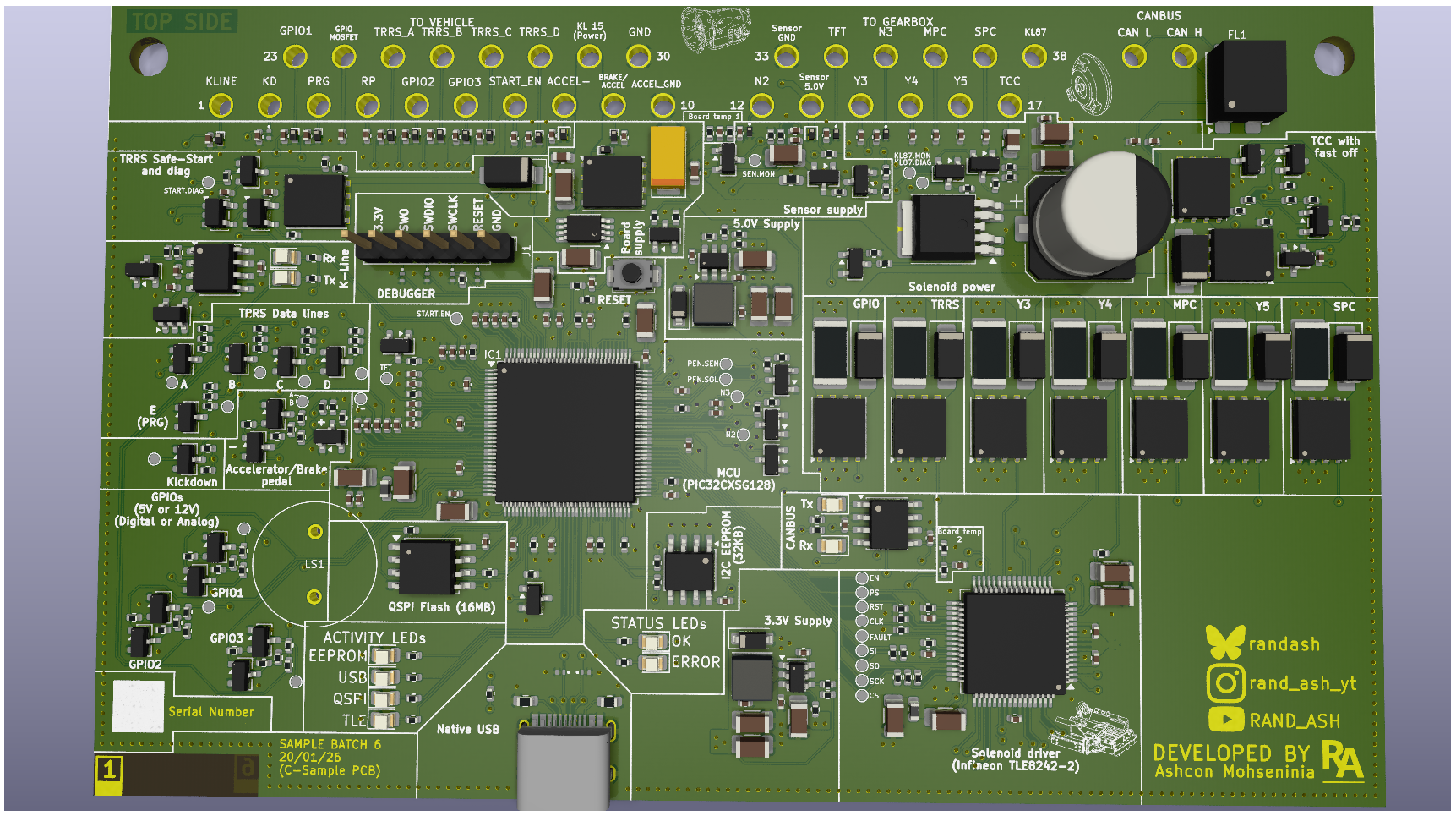
¶ Upgrades compared to 1.x boards
- Replaced ESP32 with PIC32CXSG automotive-grade processor
- Infineon TLE8242-2 for solenoid control and error detection
- 16MB external QSPI flash
- 32KB dedicated EEPROM
- 6 layer PCB
- Native USB - No more UART
- Firmware flashing via bootloader (USB/CAN/KLINE), or SWD (Debug header)
- Debug via SWD support for developers and contributers!
- Firmware written from the ground-up in Rust
- TCC Zener circuit built-in
- Add K-Line for diagnostics
- Multiple safety concepts to align better with the original Siemens EGS Unit
- Solenoid power monitoring and shutoff
- External sensor power monitoring and shutoff
- Current monitoring, short circuit and open circuit monitoring for each solenoid via TLE8242
- All inputs have ESD and over-voltage protection
- TRRS shifter start logic has hardware to physically prevent vehicle start in the event of a faulty shifter
- Reverse voltage protection
- TCC Zener circuit diagnosis via Zener spike counting
- Bigger CAN Choke (Stronger connection to PCB)
- 3x Custom inputs (Accepting either 5-15V inputs, Analog or digital)
- Add accelerator pedal input (Potentiometer input)
¶ V1.3 Rev B (23/05/26)
A minor iteration of the 1.3 PCB to reflect the current availability of parts in 2026, designed to be 100% software compatible with the existing 1.3 PCB software, whilst offering some small improvements and a more refined design
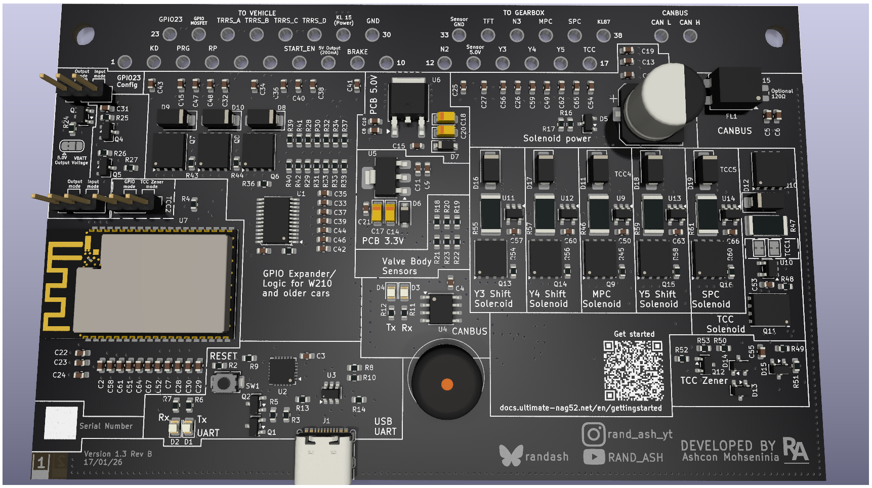
- Improved EGS connector footprint design
- Switch to LDOs for reduced PCB noise
- Optimized layout
- Switched to DSON footprint MOSFETs
- Integrated TCC Zener circuit (Only Available when NOT using GPIO23 output)
- Better solenoid power supply
- Larger CAN Filter to avoid it falling off the PCB
- Lower noise, resulting in better ADC readings
- Removed solenoid LEDs
- Added 5.0V output on the Vehicle harness side (Pin 8)
¶ Schematic and build files
¶ V1.3 (12/12/22)
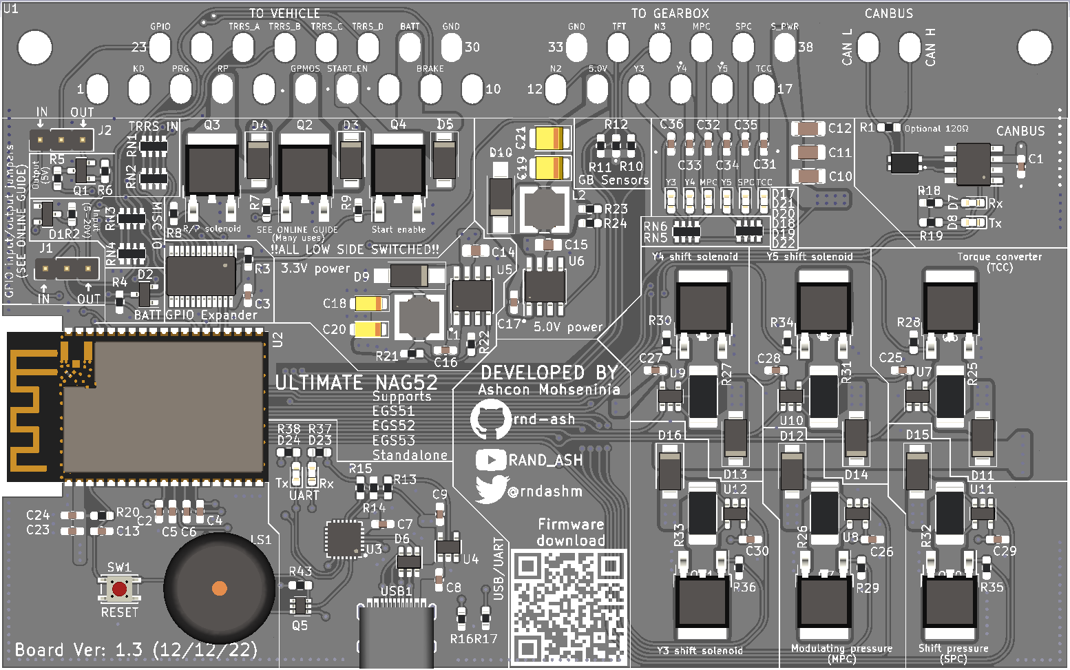
- Switched all basic SMD components (Capacitors and resistors), for higher temperature rated ones, in order to better handle engine bay installations
- Added LEDs for CAN, UART and Solenoids
- Added general purpose N-channel MOSFET on pin 6
- Added multi-use IO for pin 23 (Allows for reading G-class' output shaft sensor, or driving a speed sensor in some W124 applications)
- Added QR code on PCB silkscreen for firmware download link
¶ Schematic and build files
¶ V1.2 (07/07/22)
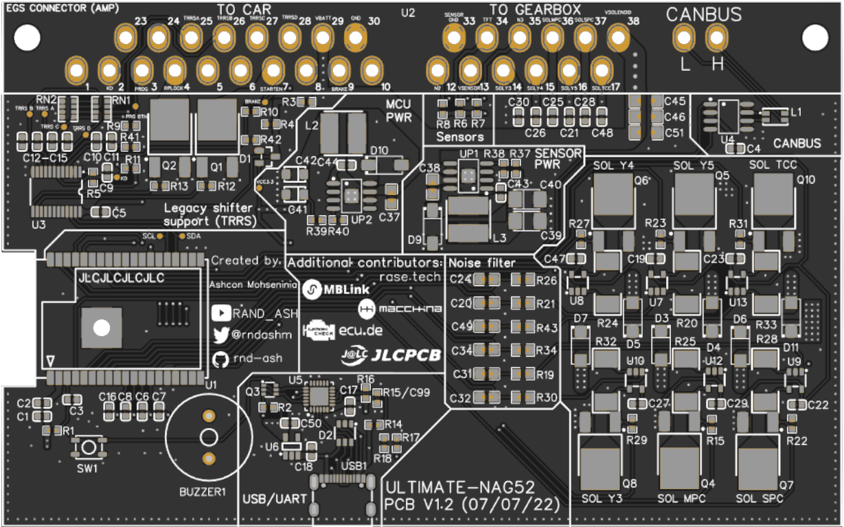
- Added legacy shifter support. This adds support for W210 generation of vehicles, and some early cars built from 2000. This includes a GPIO expander which reads data from the TRRS data lines, the Kick-down, Brake and Program button inputs, and outputs for start enable and R/P shifter solenoid.
- Switch CP2104 for CP2102 UART bridge
- Add ESD Diode to PCB
- Switched buck converters to more modern circuity
- Removed all electrolytic capacitors in favour of Tantalum ones
¶ Schematic and build files
Capacitors C20, C24, C31, C32, C34, and C49 must be removed! (Found to make current monitoring worse)
¶ V1.1 (12/12/21)
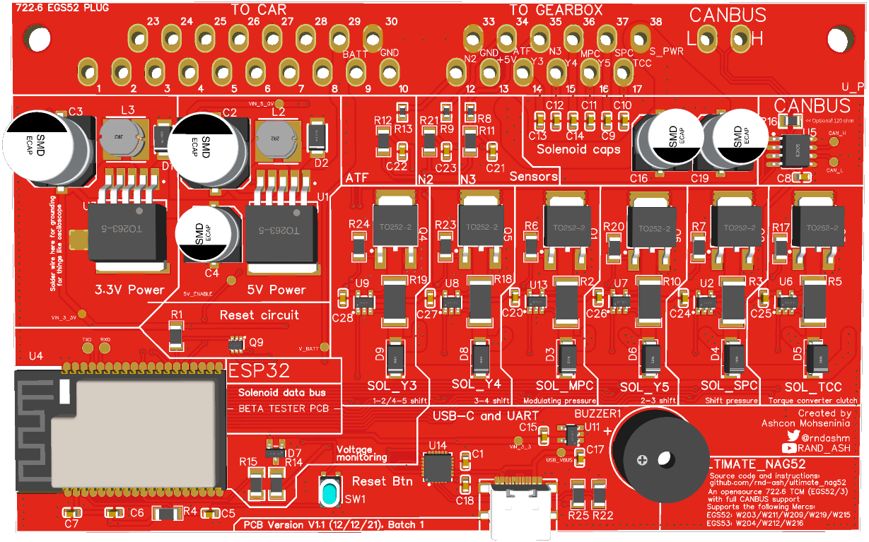
- Initial PCB made publicly available for testing